Focused on the innovative development of film capacitors for 50 years,
- 0049 - 15736573893 / 0086-519-85760515
- evayan@cje-capacitor.com / yjp@cje-capacitor.com


DC-Link metallized film capacitors for energy vehicles
Look at PDF:QCB61新能源汽车用金属化膜滤波电容器.pdf

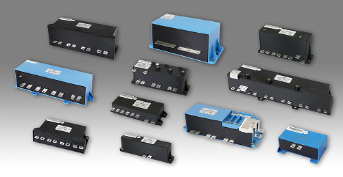
CJE has technical experience in designing and manufacturing film capacitor for decades, adopts independent intellectual property rights of national patent technology, researches and develops EV and HEV electric drive controller capacitor used for New energy vehicles to promote ideas of energy saving and environmental protection .
The capacitors’ rated voltage range is 200 ~ 1200VDC, capacitance range is from 200 to 2000uF, can provide the film capacitance solution for EV/HEV electric drive controller with different levels of power between 10 kw to 160 kw.
These capacitors are made of metallized polypropylene film design , with excellent self-healing properties , can effectively avoid the over-voltage lead to product breakdown ; capacitor operating temperature range up to -40 ~ 105℃.
After adopt the original designing and manufacturing technology, the capacitors’ equivalent series resistance is very low (as low as 0.1 mΩ less), the RMS current load capacity can be up to 250 A or more.
These capacitors have very small equivalent series inductance ( as low as 5nH less ) , and generally are made of laminated busbar technology built. Especially suitable for direct contact with the IGBT mounting , can be omitted conventional buffer capacitors, DC bus, which greatly simplifies the installation structure and installation procedures, but how compact controller greatly improved.
According to the needs of customers, we can integrate the "Y" type capacitor to suppress common-mode interference within capacitor.
Note: Because the battery voltage, the drive power and so different, electric drive controller space dimensions, the internal layout is also vastly different, these capacitors are generally highly customized products. Be sure to provide as much capacitance associated with the electrical characteristics, mechanical with other information, and with our R & D team to maintain close communication .
Your demand is our development power!
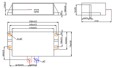
30kw bus bar capacitors for electric control of new energy vehicles
Representative Descriptions: QCB61 500VDC-250uF
Technical data
| Reference Standard | GB/T17702-2013(IEC 61071:2007);AEC Q200D | |
| Climatic Category | 40/105/21 | |
| Operating Temperature Range | -40℃ ~ 105℃ (θhs) | |
| Storage Temperature Range | -40℃ ~ 105℃ | |
| (UNDC) Rated Voltage | 500Vdc | |
| (CN) Rated Capacitance | 250μF | |
| Capacitance Tolerance | K:±10% | |
| Voltage Proof | 极间 Between Terminals : | 1.5UN(10S, 20±5℃) |
| 极壳之间 Between Terminals and Case : | 3000Vac(10s, 50Hz,20±5℃) | |
| Y电容极间 Between Terminals @ Clase Y: | 3000Vdc(2s,20±5℃) | |
| tanδd | 2×10⁻⁴ | |
| Insulation Resistance | ≥120MΩ @ 100VDC,60s,20±5℃ | |
| ESR | ≤0.6mΩ @ 10kHz | |
| Ls | ≤13nH (Measure under the holes) | |
| Max.Irms for DC | 120A | |
| Max.ripple Irms | 80A | |
| Î | 2500A | |
| Îs | 6000A (non-repetitive) | |
| Us | 650V | |
| Creepage distance | 6mm | |
| Electrical distance | 6mm | |
| Expected lifetime | 参考寿命曲线 Refer to expected lifetime curve | |
| Failure rate | 50FIT | |
| Dimension (L×w×h) | 130mm×75mm×38mm | |
| Weight | ≈0.5KG | |
θcase:Temperature of case
ESR: The sum of all ohmic resistances occurring inside the capacitor θhs=θcase+Irms2×ESR×Rthhc
Outline Drawing

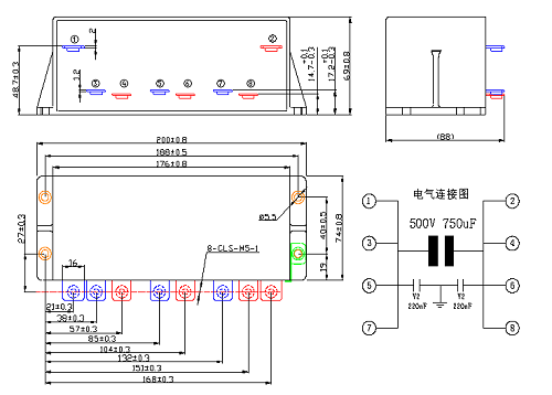
60kw bus bar capacitors for electric control of new energy vehicles
Representative Descriptions:QCB61 500VDC-750uF
echnical data
| Reference Standard | GB/T17702-2013(IEC 61071:2007);AEC Q200D | |
| Climatic Category | 40/105/21 | |
| Operating Temperature Range | -40℃ ~ 105℃ (θhs) | |
| Storage Temperature Range | -40℃ ~ 105℃ | |
| (UNDC) Rated Voltage | 500Vdc | |
| (CN) Rated Capacitance | 750μF | |
| Capacitance Tolerance | K:±10% | |
| Voltage Proof | 极间 Between Terminals : | 1.5UN(10S, 20±5℃) |
| 极壳之间 Between Terminals And Case : | 3000Vac(10s, 50Hz,20±5℃) | |
| Y电容极间 Between Terminals @Clase Y: | 3000Vdc(2s,20±5℃) | |
| tanδd | 2×10⁻⁴ | |
| Insulation Resistance | ≥40MΩ @ 100VDC,60s,20±5℃ | |
| ESR | ≤0.4mΩ @ 10kHz | |
| Ls | ≤12nH (Measure under the holes) | |
| Max.Irms for DC | 200A | |
| Max.ripple Irms | 180A | |
| Î | 6000A | |
| Îs | 12000A (non-repetitive) | |
| Us | 650V | |
| Creepage distance | 6mm | |
| Electrical distance | 6mm | |
| Expected lifetime | 参考寿命曲线 Refer to expected lifetime curve | |
| Failure rate | 50FIT | |
| Dimension (L×w×h) | 176mm×74mm×69mm | |
| Weight | ≈1.25KG | |
θcase:Temperature of case
ESR: The sum of all ohmic resistances occurring inside the capacitor θhs=θcase+Irms2×ESR×Rthhc
Outline Drawing

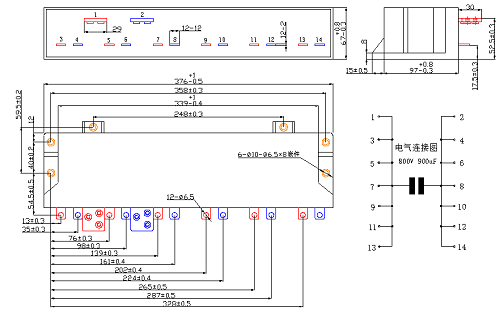
100kw bus bar capacitors for electric control of new energy vehicles
Representative Descriptions: QCB61 800VDC-900uF
Technical data
| Reference Standard | GB/T17702-2013(IEC 61071:2007);AEC Q200D | |
| Climatic Category | 40/105/21 | |
| Operating Temperature Range | -40℃ ~ 105℃ (θhs) | |
| Storage Temperature Range | -40℃ ~ 105℃ | |
| (UNDC) Rated Voltage | 800Vdc | |
| (CN) Rated Capacitance | 900μF | |
| Capacitance Tolerance | J:±5% | |
| Voltage Proof | 极间 Between Terminals : | 1.5UN(10S, 20±5℃) |
| 极壳之间 Between Terminals And Case : | 3000Vac(10s, 50Hz,20±5℃) | |
| Y电容极间 Between Terminals @Clase Y: | 3000Vdc(2s,20±5℃) | |
| tanδd | 2×10⁻⁴ | |
| Insulation Resistance | ≥35MΩ @ 100VDC,60s,20±5℃ | |
| ESR | ≤0.3mΩ @ 10kHz | |
| Ls | ≤15nH (Measure under the holes) | |
| Max.Irms for DC | 400A | |
| Max.ripple Irms | 380A | |
| Î | 10000A | |
| Îs | 25000A (non-repetitive) | |
| Us | 1050V | |
| Creepage distance | 10mm | |
| Electrical distance | 10mm | |
| Expected lifetime | 参考寿命曲线 Refer to expected lifetime curve | |
| Failure rate | 50FIT | |
| Dimension (L×w×h) | 339mm×97mm×67mm | |
| Weight | ≈3.75KG | |
θcase:Temperature of case
ESR: The sum of all ohmic resistances occurring inside the capacitor θhs=θcase+Irms2×ESR×Rthhc
Outline Drawing


The company has a professional research institute and a team with high-level researching & developing experience

The company has many national level qualifications

Inspire people with enormous career , attractive people with favorable treatment, condense people with excellent culture , create conditions to achieve success

Provide customers with high quality, efficient, safety and environmentally friendly services and products


 0049 - 15736573893